ECE Projects
|
ECE Projects |
Event Detection Circuits Math Function Circuits Measurement Circuits Motor Control Circuits Power Supply Circuits Sensing Circuits Special Function Circuits Switching Circuits Timing Circuits ToneWave Generators |
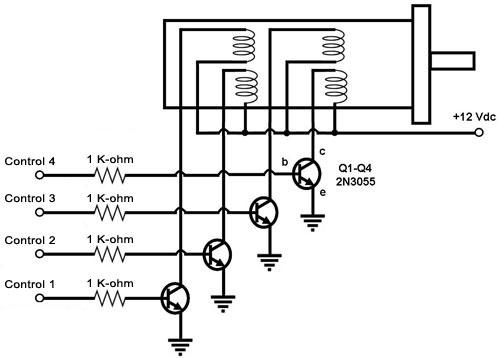
4-Phase Stepper Motor Transistor Driver
Figure 1. Circuit Diagram for a 4-Phase Stepper Motor Driver Using NPN Transistors This is a circuit for driving a 4-phase stepper motor using 4 digital signals from a source of digital control signals such as a computer or a stepper motor controller IC. A stepper motor is actuated by energizing its internal windings one at a time, i.e., the motor shaft turns a fraction of a revolution every time a winding is energized. The shaft of a stepper motor 'locks' into place after the incremental turn is made, even if the power to the winding is sustained. Thus, to turn the motor shaft continuously, the windings must be energized sequentially in continuous cycles. The basic pattern for energizing the windings in sequence is conveniently achieved by digital means, such as from the output port of a computer or from the digital outputs of a stepper motor controller IC. These digital signals, however, are not strong enough to drive the windings of a stepper motor directly, so there's a need to 'amplify' the current capacity of these signals. This is achieved by using these digital signals to drive the base of a power transistor, which in turn drives the windings of the stepper motor, as shown in Figure 1 above. In this circuit, a logic '1' is fed into the base of a transistor to energize the winding that's connected to the transistor. This logic '1' input turns on the transistor, allowing current to pass through the winding from the 12V supply to ground, energizing the winding in the process. Inputting a logic '0' to the base of the transistor turns it off, cutting off the current flow through the winding. |