ECE Projects


Electronic Projects

       AudioRF Circuits 
     
      Event Detection Circuits 
         
      Math Function Circuits 
         
      Measurement Circuits 
    
      Motor Control Circuits 
         
      Power Supply Circuits 
         
      Sensing Circuits 
         
      Special Function Circuits 
         
      Switching Circuits 
     
      Timing Circuits 
         
      ToneWave Generators 

555-based Siren Circuit

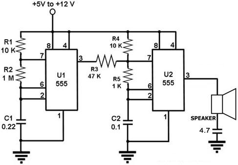
Figure 1.  Circuit Diagram for a Siren using 555 Timer IC's

This is a warbler siren circuit that uses two LM555 timer IC's.  A single LM556 IC, which contains two 555 timers inside it, may also be used for this circuit.

Both the 555 timer IC's in this circuit are configured as astable multivibrators, i.e., they both generate a continuous signal of given frequency. 


U2 is configured to have a much higher frequency than U1.  U2 provides the main siren sound to the speaker, while U1 modulates the output of U2 to give it a warbling effect.  What U1 does is to interrupt U2 periodically, causing its otherwise continuous sound output to warble.

The pitch and speed of the siren may be adjusted by varying the values of R5 and R2.  To increase the volume of the siren, an amplifier may be inserted between U2 output and the speaker.