ECE Projects
|
ECE Projects |
Electronic Projects
AudioRF
Circuits |
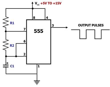
555 Timer Astable Multivibrator Circuit; Pulse Generator Circuit
Figure 1. Astable Multivibrator Circuit Diagram Using the 555 Timer This circuit diagram shows how a 555 timer IC is configured to function as an astable multivibrator. An astable multivibrator is a timing circuit whose 'low' and 'high' states are both unstable. As such, the output of an astable multivibrator toggles between 'low' and 'high' continuously, in effect generating a train of pulses. This circuit is therefore also known as a 'pulse generator' circuit. In this circuit, capacitor C1 charges through R1 and R2, eventually building up enough voltage to trigger an internal comparator to toggle the output flip-flop. Once toggled, the flip-flop discharges C1 through R2 into pin 7, which is the discharge pin. When C1's voltage becomes low enough, another internal comparator is triggered to toggle the output flip-flop. This once again allows C1 to charge up through R1 and R2 and the cycle starts all over again. C1's charge-up time t1 is given by: t1 = 0.693(R1+R2)C1. C1's discharge time t2 is given by: t2 = 0.693(R2)C1. Thus, the total period of one cycle is t1+t2 = 0.693 C1(R1+2R2). The frequency f of the output wave is the reciprocal of this period, and is therefore given by: f = 1.44/(C1(R1+2R2)), wherein f is in Hz if R1 and R2 are in megaohms and C1 is in microfarads. |
|