ECE Projects
|
ECE Projects |
555 Timer Monostable Multivibrator Circuit
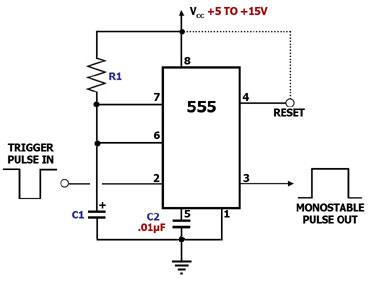
Figure 1. Monostable Multivibrator Circuit Diagram Using the 555 Timer This circuit diagram shows how a 555 timer IC is configured to function as a basic monostable multivibrator. A monostable multivibrator is a timing circuit that changes state once triggered, but returns to its original state after a certain time delay. It got its name from the fact that only one of its output states is stable. It is also known as a 'one-shot'. In this circuit, a negative pulse applied at pin 2 triggers an internal flip-flop that turns off pin 7's discharge transistor, allowing C1 to charge up through R1. At the same time, the flip-flop brings the output (pin 3) level to 'high'. When capacitor C1 as charged up to about 2/3 Vcc, the flip-flop is triggered once again, this time making the pin 3 output 'low' and turning on pin 7's discharge transistor, which discharges C1 to ground. This circuit, in effect, produces a pulse at pin 3 whose width t is just the product of R1 and C1, i.e., t=R1C1. The reset pin, which may be used to reset the timing cycle by pulling it momentarily low, should be tied to the Vcc if it will not be used. |
|