ECE Projects
|
ECE Projects |
Electronic Projects AudioRF
Circuits |
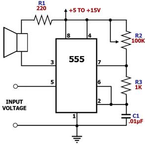
555 Timer Voltage-Controlled Oscillator
Figure 1. 555 Timer Voltage-Controlled Oscillator Circuit Diagram This circuit is a voltage-controlled oscillator (VCO) that uses the 555 timer IC as the main component. As expected, the 555 timer is configured as an astable multivibrator to be able to serve as an oscillator. An astable multivibrator is just a timing circuit whose output oscillates between 'low' and 'high' continuously, in effect generating a train of pulses. The difference of this circuit with the basic 555 astable circuit is that its 555's pin 5 is tied to an external voltage source. Pin 5 is the 555's control voltage pin, which allows the user to directly adjust the threshold voltages to which the pin 2/pin 6 input voltages are compared by the 555's internal comparators. Since the outputs of these comparators control the internal flip-flop that toggles the output of the 555, adjusting the pin 5 control voltage also adjusts the frequency at which the 555 toggles its output. Increasing the input voltage at pin 5 decreases the output oscillation frequency while decreasing the input voltage increases the output oscillation frequency. |
|