ECE Projects
|
ECE Projects |
Electronic Projects AudioRF
Circuits |
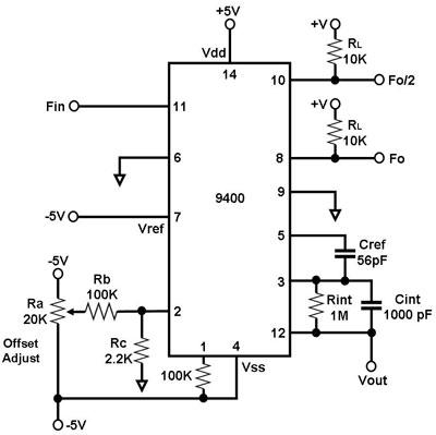
9400-Based Frequency-to-Voltage Converter
Figure 1. Schematic Diagram for a Frequency-to-Voltage Converter Using the 9400 Figure 1 shows the basic application circuit for using the 9400 in frequency-to-voltage (F-V) conversion. The 9400 is a 14-pin voltage-to-frequency/frequency-to-voltage converter IC. Note that the circuit in Figure 1 needs two voltage supplies (+5V and -5V). The output voltage Vout of this circuit varies in linear proportion to the input frequency Fin, which can range from DC to 10 kHz. Also, the output of this circuit may exhibit a ripple that is inversely proportional to the value of Cint and the input frequency. Thus, if the input frequency is low, Cint must be increased to reduce the ripple at the output. Another way to reduce the output ripple of this circuit is by using a ripple eliminator circuit. |
|