ECE Projects
|
ECE Projects |
Electronic Projects AudioRF
Circuits |
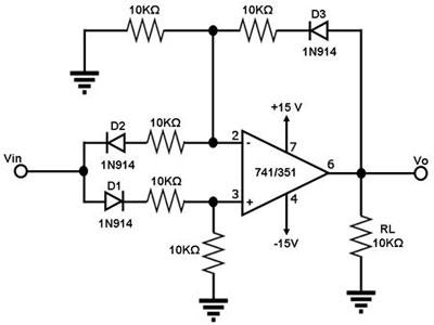
Absolute Value Circuit
Figure 1. Schematic Diagram for an 'Absolute Value' Circuit Figure 1 shows a circuit for generating an output voltage that is the absolute value of the input voltage. This means that the output of this circuit swings in the positive range only, whatever the polarity of the input signal is. When an AC input signal Vin is in the positive cycle, D2 is off, causing the inverting input to be isolated from Vin. With D1 'on', and with the voltage drops across D1 and D3 being equal, and with the voltage levels at the two inputs of the op-amp being equal, Vo becomes equal to Vin. This is because the resistor network between Vo to ground and that between Vin and ground are identical. In short, when the input voltage is swinging positively, the output is just equal to it. When an AC input signal Vin is in the negative cycle, D1 is off, causing the non-inverting input to be isolated from Vin. With D2 'on', and with the voltage drops across D2 and D3 being equal, and with the voltage levels at the two inputs of the op-amp being equal (both are at 0 V), the current from the output is equal to the current into the input. These equal currents in opposite directions through identical paths means that Vo = -Vin. Since Vin is negative, Vo is positive. In short, when the input voltage is swinging negatively, the output is just its positive copy. Needless to say, this circuit may be used as a full-wave rectifier for sinusoidal inputs. |
|