ECE Projects
|
ECE Projects |
Electronic Projects AudioRF
Circuits |
Bar Graph Voltage Monitor Circuit
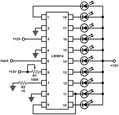
Figure 1. Diagram for a Voltage Monitor with a 'Bar Graph' Display This is a circuit for monitoring a voltage level and displaying it in the form of a bar graph. The heart of this circuit is the LM3914 dot/bar display driver, an IC that senses an analog voltage and drives the LED's connected to its 10 outputs linearly according to the sensed voltage. The LM3914 has an internal reference voltage, which is used by an internal resistor network to produce the 10 different levels of voltage to which the sensed voltage is compared. Voltage comparison of these individual levels to the sensed voltage is accomplished by 10 internal comparators. The sensed voltage is fed into pin 5, the signal input pin of the LM3914. This voltage is internally buffered before it is fed to the inverting input of each of the 10 comparators, so it can be compared to each of voltage levels set by the resistor network. The resistor network voltages are fed to the non-inverting inputs of the comparators. The output of a comparator goes 'low' if the sensed voltage exceeds the internally generated voltage to which it is compared, thereby lighting up the LED connected to it (note the orientation of the LED's connected to the outputs). Thus, the higher the sensed voltage, the more LED's are lit, and the higher the 'bar graph' is. Note that the power supply of the LM3914 in this circuit must be different from the voltage being sensed. |
|