ECE Projects
|
ECE Projects |
Electronic Projects AudioRF
Circuits |
Basic Astable Multivibrator Circuit
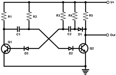
Figure 1. Circuit Diagram for a Basic Astable Multivibrator The circuit in Figure 1 is that of a basic astable multivibrator. As its name implies, the output of this circuit is not stable, i.e., it continuously toggles between logic '1' and logic '0' at a rate set by the resistors and capacitors in the circuit. Assume, for instance, that the output is low. In this state, transistor Q2 is 'on' while transistor Q1 is 'off'. Meanwhile, this allows capacitor C2 to charge up through resistor R3, continuously increasing the base voltage of transistor Q1. Eventually, the base voltage of Q1 becomes high enough to turn Q1 on. Once Q1 turns on, it pulls Q2's base voltage to 'low', turning 'off' Q2. This causes the output to go 'high' because of the pull-up resistor R5. As Q1 conducts, C1 charges up through R2, continuously increasing the base voltage of transistor Q2. Eventually, the base voltage of Q2 becomes high enough to turn Q2 on. Once Q2 turns on, the output goes 'low' again and pulls Q1's base voltage to 'low', turning 'off' Q1. This cycle of toggling the output between 'low' and 'high' goes on indefinitely as long as the circuit is powered. The frequency at which the output oscillates is determined of course by the rates at which C1 and C2 charge up. The rate at which C1 charges up depends on the values of C1 and R2 (the higher their values the slower is the charging up), while that of C2 depends on the values of C2 and R3. |
|