ECE Projects
|
ECE Projects |
Electronic Projects AudioRF
Circuits |
Basic Bistable Multivibrator Circuit (Flip-Flop)
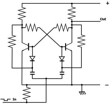
Figure 1. Basic Bistable Multivibrator (Flip-flop) Circuit Figure 1 shows the basic circuit for a bistable multivibrator or flip-flop. A bistable multivibrator is a digital circuit whose output may be toggled between its 'high' and 'low' state. The output is stable in either state (hence the name), and will only change with the appropriate trigger signal at the input. A circuit that behaves in this manner is also commonly referred to as a 'flip-flop'. In the circuit in Figure 1, assume that the output is 'high'. This output state ensures that the left NPN transistor is conducting, since current is being supplied to its base. Since the left transistor is conducting, its collector voltage is 'low'. This is also the base voltage of the right NPN transistor, so the latter will be in its cut-off state since no current is being fed into its base. Now assume that a low-going pulse is applied at the input of the circuit. This pulse will pull down the base voltage of the left transistor, causing it to go into 'cut-off'. This pulls up the base voltage of the right transistor, driving it into conduction. The conducting right transistor pulls the output to 'low', and thus changing its state. The diodes and capacitors tied to the bases of the transistors ensure that the conducting transistor will change state first (from 'on' to 'off') to drive the change in state of the non-conducting transistor (from 'off' to 'on'), thereby ensuring that a low-going pulse will always trigger a change in the output of the circuit. This difference in response times is due to the fact that the capacitor connected to the conducting transistor is discharged (the discharge path is through the collector of the conducting transistor), while the capacitor connected to the non-conducting transistor is charged. |
|