ECE Projects
|
ECE Projects |
Electronic Projects AudioRF
Circuits |
Butterworth High-Pass Filters
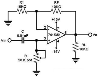
The circuit shown in Figure 1 is a first-order Butterworth high-pass filter. A high-pass filter is a circuit that blocks signals with frequencies lower than a cut-off frequency fc. The circuit in Figure 1 uses an op-amp configured as a non-inverting amplifier, with an RC circuit at the non-inverting input to do the filtering of the low-frequency signals. The cut-off frequency fc of this circuit is determined by R and C, i.e., fc = 1/{2p(RC)}. The pass-band gain Gp of this filter is given by: Gp = 1 + (RF/R1). Thus, if the frequency f of the input signal is higher than fc, Vo ˜ Gp x Vin. If f = fc, Vo ˜ 0.707 Gp x Vin. If f < fc, Vo < Gp x Vin
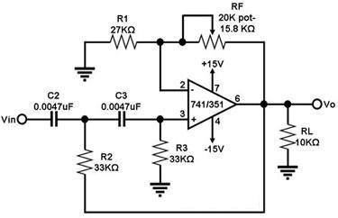
Figure 2. Circuit Diagram for a Second-Order Butterworth High-Pass Filter As the frequency of the input signal goes lower than fc, the gain of the first-order Butterworth high-pass filter in Figure 1 decreases at a rate of -20 dB/decade. If one desires a better high-pass frequency response than this, the second-order Butterworth high-pass filter in Figure 2 can be used. This circuit exhibits a -40 dB/decade roll-off at f<fc, wherein fc = 1/{2p x sqrt(R2R3C2C3)}. Also, for this circuit, the magnitude of Vo/Vin = (1+RF/R1)/(sqrt(1+(fc/f)4)). |
|