ECE Projects
|
ECE Projects |
Electronic Projects AudioRF
Circuits |
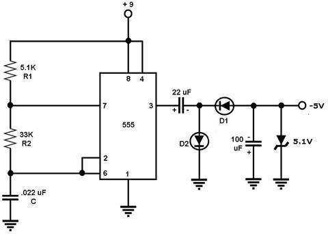
Circuit for Getting -5V from +9V
Figure 1. Circuit for deriving -5V from a +9V Supply This is a circuit that derives -5V from a +9V supply. Its main component is the 555 timer configured as an astable multivibrator. This circuit is actually based on the basic circuit for 555-based polarity inverter. When the 555 output (pin 3) goes 'high', the 22 uF capacitor at its output charges up through D2 to a level close to 9V. When the output goes 'low', C2 can not discharge to pin 3 through D2 because D2 is 'off'. C2 discharges its voltage to pin 3 through D1, causing the 100 uF capacitor to charge up. Note that the current flow during the charging up of the 100 uF puts its negative terminal at a more negative voltage than its positive terminal (which is grounded). When the 555 output goes 'high' again, the voltage across the 100 uF is not discharged because the capacitor is isolated by D1. The 5.1 V zener diode at the final output of the circuit limits the output to just about -5 V. Thus, this circuit is just the 555-based polarity inverter circuit with a -5V voltage limiter at the output. Note that this circuit is limited in the current that it can supply to the load (just a few milliamps). |
|