ECE Projects
|
ECE Projects |
Electronic Projects AudioRF
Circuits |
Clipper Circuit
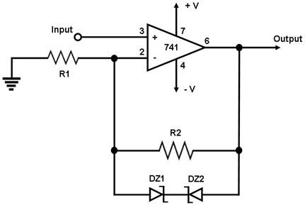
Figure 1. Schematic Diagram for a Clipper Circuit This is a circuit that clips portions of the input voltage waveform that go beyond preset lower and upper limits, hence the name 'clipper'. The lower and upper voltage limits are set by the zener breakdown voltages of zener diodes DZ1 and DZ2. For instance, if the zener diodes used have a zener voltage of 5 V, then any part of the input waveform that exceeds -5V/+5V is clipped at -5V/+5V. The circuit uses a 741 operational amplifier IC configured as a non-inverting amplifier, except that a pair of back-to-back zener diodes is connected across the feedback resistor R2. This pair of zener diodes prevents the voltage across R2 from going beyond the zener voltages of the diodes in either direction. During the positive cycle of the input waveform, DZ1 is always conducting while DZ2 is 'off' as long as the waveform does not exceed DZ2's zener voltage, causing the output of the 741 to follow the input. If the input exceeds DZ2's zener breakdown voltage, DZ2 starts conducting, thereby 'clipping' the input waveform at this breakdown voltage level. The output starts following the input waveform again when the input goes below this limit.
|
|