ECE Projects
|
ECE Projects |
Electronic Projects AudioRF
Circuits |
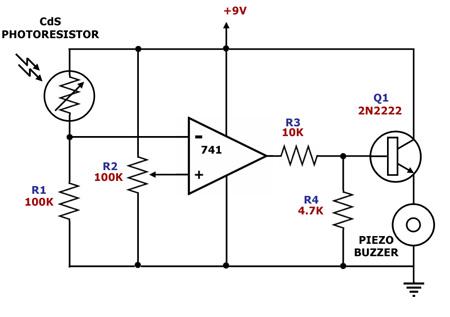
Darkness-Activated Buzzer Circuit
Figure 1. Darkness-Activated Buzzer Circuit Diagram This circuit is for a simple buzzer that is activated by darkness, i.e., the buzzer is off when there's light and on when it is dark. A general-purpose operational amplifier, the 741, is used as a comparator that determines whether it is dark enough to turn on a self-oscillating piezoelectric buzzer. Its inverting input is connected to a photoresistor, a component whose resistance decreases as more light shines on it. Its non-inverting input, on the other hand, is connected to an almost fixed voltage, i.e., a proportion of the supply voltage as set by trimmer resistor R2. If there is ample light shining on the photoresistor, the buzzer is quiet. As less light shines on the photoresistor, its resistance increases and causes the voltage across R1 to decrease. At a certain level of lighting, the voltage across R1, which is also the voltage at the inverting input of the 741, becomes smaller than the voltage at the non-inverting input. At this point, the 741 is triggered to output a 'high' level, turning on Q1. Q1 then activates the self-oscillating piezoelectric buzzer. |
|