ECE Projects
|
ECE Projects |
Electronic Projects AudioRF
Circuits |
Comparator-based Light Detector
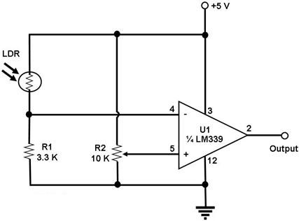
Figure 1. Circuit Diagram for a Light Detector This is light detecting circuit that uses a voltage level comparator. The IC used in the example is the LM339, which is a quad comparator IC. Only one of the 4 internal comparators of this IC is used in this circuit. The light sensing component of this circuit is a light detecting resistor, or LDR. This is just a photo-sensitive component that changes its resistance according to the light shining on it. The more light that shines on it, the lower is its resistance. The non-inverting input of the comparator is fixed by R2 as a percentage of the power supply. R2 is therefore used to set the threshold voltage of the comparator. The voltage at the inverting input of the comparator is determined by LDR and R1. The more light shining on the LDR, the lower is its resistance, and the higher is the voltage at this input. The comparator's output changes state every time the voltage at the inverting input exceeds or falls below the threshold voltage set at the non-inverting input. |
|