ECE Projects
|
ECE Projects |
Electronic Projects AudioRF
Circuits |
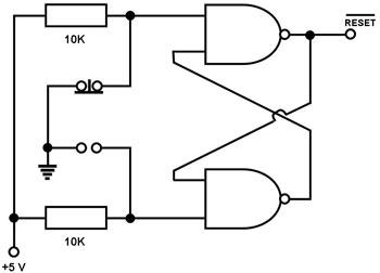
Digital Reset Switch
Figure 1. Circuit Diagram for a Simple Digital Reset Switch The circuit in Figure 1 is a very simple digital 'reset' switch commonly used in the 1980's to provide the 'reset' signal to simple microprocessor-based systems. The reset pin of a microprocessor must be held high during normal operation (assuming that its reset pin is active-low, of course). When the microprocessor needs to reinitiate the program sequence and reset its peripheral devices, a low-going reset pulse needs to be applied to its reset pin. To avoid unintentional or improper resetting of the system, the input to the reset pin must be both clean and stable. The circuit above achieves this. The two flip-flops of the circuit are connected in such a way that their outputs stabilize each other. For instance, during normal operation (button is not pressed), the reset pin is high. This is fed back to the input of the lower flip-flop, ensuring that its output is 'low'. This 'low' output is fed back to the input of the upper flip-flop, which ensures that its output is 'high'. When the button is pressed, one of the outputs of the lower flip-flop is pulled 'low', causing its output to go 'high'. This causes one of the inputs to the upper flip-flop to go high, driving its output to go 'low' and, thus, giving the low-going reset pulse. This 'low' output is fed back to the lower flip-fop, which ensures that its output remains high. When the button is released, it pulls down one of the inputs of the upper flip-flop to 'low' again, restoring the reset output to 'high'. |
|