ECE Projects
|
ECE Projects |
Electronic Projects AudioRF
Circuits |
Electronic Combination Lock Circuit
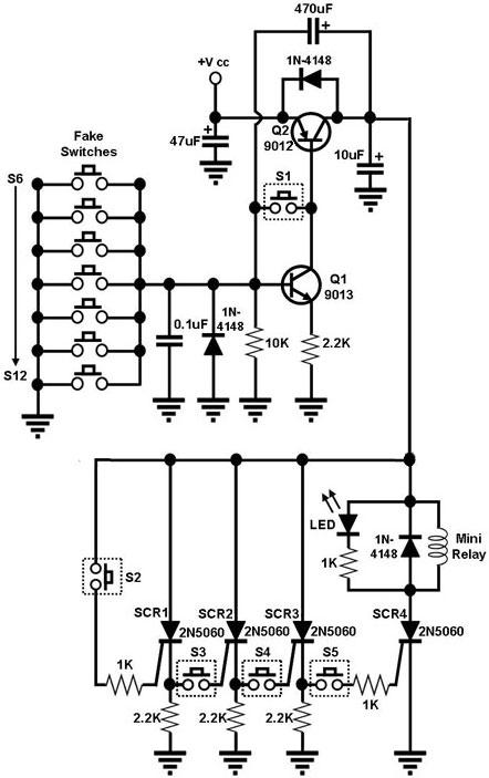
Figure 1. Circuit Diagram for an Electronic Combination Lock Figure 1 shows a circuit for an electronic combination lock that can be used to limit the access to and utilization of electrical equipment or electronic appliances to authorized people only. The electrical/electronic equipment that this circuit 'locks' is attached to the AC supply through the contacts of a mini-relay at the output of the circuit. Thus, the equipment can only be powered on if the mini relay is energized. The relay is energized by SCR4, which is only triggered by S5 and a conducting SCR3, which is only triggered by S4 and a conducting SCR2, which is only triggered by S3 and a conducting SCR1, which is only triggered by S2. Thus, the relay will only be energized if the keys S2, S3, S4, and S5 are pressed in that sequence. If one of fake switches is triggered before the correct sequence is completed, Q1 will be turned off, which will also cause Q2 to turn off. This cuts off the current flowing to the SCR's, causing all of them to turn off. The sequence then needs to be restarted and completed in order to get the circuit 'unlocked'. Needless to say, the label and arrangement of the true and fake switches may be chosen to reflect the desired code. |
|