ECE Projects
а
|
ECE Projects |
а |
| а |
Electronic Projectsа аааааAudioRF
Circuitsа |
Event Interruption Alarm Circuit
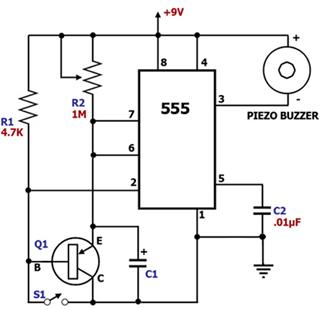
Figure 1.а Event Interruption Alarm Circuit Diagram
The main component of this circuit is the 555, a versatile timer IC.а It is configured as a monostable multivibrator, i.e., a circuit which will output a single pulse at pin 3 every time pin 2 is pulled 'low'. Each time the event occurs, switch S1 closes, discharging C1 to ground through Q1 and triggering pin 2 to force an internal flip-flop to set pin 3 to a 'high' level.а At this stage, the buzzer is silent since both of its terminals are 'high'.а Meanwhile, capacitor C1 charges up again through R2 as soon as S1 is opened.а The voltage across C1 will continue to rise unless S1 is momentarily closed again to discharge it through Q1.а Momentarily closing S1 regularly before the time limit is up will prevent C1 from charging up to the critical voltage level, thereby keeping the buzzer silent. If, however, S1 is not closed within the set time limit, the voltage across C1 will become high enough to trigger the internal flip-flop to set pin 3 to a 'low' level.а At that point, the self-oscillating buzzer will alarm because pin 3 is now pulling one of its terminals to 'low' while the other terminal is at Vcc. |
|
а
а