ECE Projects
|
ECE Projects |
Electronic Projects AudioRF
Circuits |
Low DC-to-High DC Voltage Converter
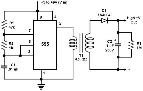
Figure 1. Circuit Diagram for a Low-to-High DC Voltage Converter This is a circuit for converting a low DC voltage into a very high DC voltage. The 555 timer IC in this circuit is configured as an astable multivibrator, i.e., it generates a continuous signal of given frequency. This periodic signal is fed into the low-side winding of a transformer. The resulting pulsating current in the low-side winding results in a high AC voltage across the high-side winding. The level of this voltage depends on the voltage ratio of the transformer used. The example above uses a transformer with a voltage ratio of 6.3V:220V, which can easily generate voltages in excess of 200 volts from a 9-volt battery. The current in the output winding is rectified using a diode, and a capacitor is used to 'smoothen' the rectified voltage waveform, producing a DC voltage. R3 is required to 'bleed' the capacitor charge to ground when the circuit is not in operation. Warning: C2 can store a high voltage, so extreme care is needed when working with this circuit (e.g., the output must not be touched). |
|