ECE Projects
|
ECE Projects |
Electronic Projects AudioRF
Circuits |
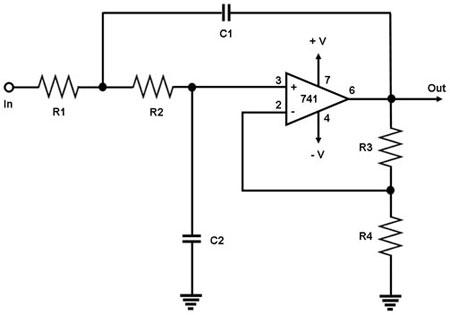
Low-Pass Filter Circuit
Figure 1. Circuit Diagram for a Low-Pass Filter This is a circuit that only allows input signals with low frequencies to pass to the output, hence the name 'low-pass filter'. All signals with high frequencies are attenuated (weakened or decreased in level) by this circuit. The circuit is an active filter that uses a 741 operational amplifier IC,withR1=R2= RandC1=C2=C. The reactance of a capacitor decreases as the frequency of the signal through it increases. Thus, in the circuit above, C2 tends to shunt high-frequency signals towards the ground, causing them to be attenuated at the output. On the other hand, the lower the frequency of the input signal, the higher are the reactances of C1 and C2, and the closer the circuit resembles a non-inverting amplifier. The gain G of this amplifier is approximately given by: G = R3/R4.
|
|