ECE Projects
|
ECE Projects |
Electronic Projects AudioRF
Circuits |
Metronome Circuit
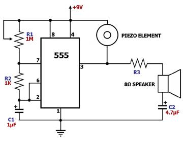
Figure 1. Metronome Circuit Diagram This circuit is for an audible metronome, which is a device that indicates musical tempo. The main component of this circuit is the 555, a versatile timer IC. It is configured as an astable multivibrator, i.e., a timing circuit whose output toggles between 'low' and 'high' continuously, in effect generating a train of pulses. The train of pulses generated by an astable multivibrator can be used to drive either a speaker or a simple, non-self-oscillating piezoelectric buzzer to generate sound. In the case of a metronome, the frequency at which these sound producing elements are driven should be low, e.g., 1 Hz to 10 Hz. Since the output frequency f of the 555 circuit above is defined by the equation f = 1.44/(C1(R1+2R2)), lower frequencies can be achieved by using high values for C1 and (R1+2R2). In the circuit above, R2 was fixed at 1 K, but a 1M-ohm variable resistor was used as R1 in conjunction with a 1 microfarad C1 to achieve the low frequency required for a practical metronome. In the circuit above, either the piezo buzzer or the speaker may be omitted, depending on the quality of sound required. |
|