ECE Projects
|
ECE Projects |
Electronic Projects AudioRF
Circuits |
Negative and Positive DC Voltage Power Supply Circuit
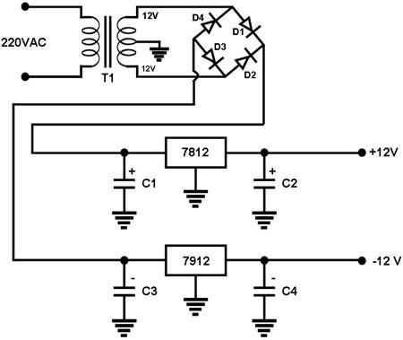
Figure 1. Circuit Diagram for a Positive/Negative Voltage Power Supply This is a power supply circuit that provides regulated +12V and -12V outputs. The diode bridge formed by D1, D2, D3, and D4 performs the rectification needed to convert the transformer's AC current into a DC current. By using the center tap of the transformer as ground, DC voltages of opposite polarities with respect to this ground can be generated from the transformer's AC current. During the 'positive' cycle, the transformer current travels through D1, charges up C1, goes to ground, charges up C3, travels through D3 and then returns to the opposite tap of the transformer. Note that the C1 voltage built up is positive with respect to ground while that of C3 is negative. During this cycle, D2 and D4 are 'off'. During the 'negative' cycle, the transformer current travels through D2, charges up C1, goes to ground, charges up C3, travels through D4 and then returns to the opposite tap of the transformer. Note that this path also gives C1 and C3 a positive and a negative voltage, respectively. During this cycle, D1 and D3 are 'off'. The C1 and C3 voltages are then fed into the 7812 (+12V regulator) and 7912 (-12V regulator) IC's to come up with regulated +12V and -12V outputs, respectively. |
|