ECE Projects
|
ECE Projects |
Electronic Projects AudioRF
Circuits |
Non-Inverting A.C. Amplifier Circuit
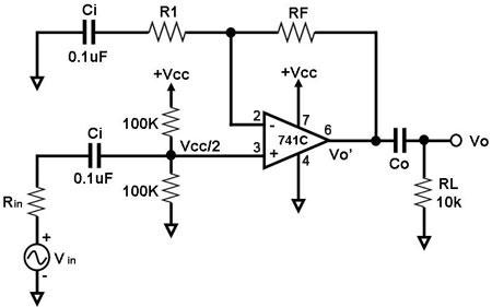
Figure 1. Circuit Diagram for a Non-Inverting AC Amplifier This is a circuit for amplifying an AC input voltage with no inversion at the output. The active component of this circuit is an operational amplifier, which is configured as a non-inverting amplifier. To ensure that the output can swing in the positive and negative directions equally, a DC voltage equal to Vcc/2 is inserted at the non-inverting input through the voltage divider formed by the 100K resistors. When Vin is an AC signal within the circuit's bandwidth, the gain G of the amplifier is determined by RF and R1, i.e., G = 1 + RF/R1. The op amp output Vo' is the sum of the DC (Vcc/2) and AC output voltages. Output capacitor Co removes the DC component of Vo', causing the final output Vo of the circuit to be a purely AC amplified copy of the input waveform, or Vo = (1 + RF/R1) Vin.
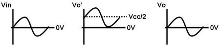
Figure 2. Input and output waveforms of the AC amplifier in Figure 1 Figure 2 graphically shows an example of how an AC input voltage is amplified by the AC amplifier shown in Figure 1. The op amp's output, Vo', is an amplified copy of the input voltage, shifted upwards by a DC component equal to Vcc/2. The final output Vo of the circuit is a purely AC amplified copy of the input waveform, since the DC component has already been removed by Co. |
|