ECE Projects
|
ECE Projects |
Electronic Projects AudioRF
Circuits |
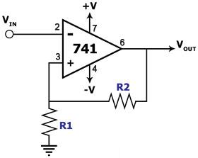
Non-Inverting Amplifier Circuit
Figure 1. Non-Inverting Amplifier Circuit Diagram This circuit uses an operational amplifier configured as a non-inverting amplifier. The main component of this circuit is the 741, a general-purpose operational amplifier. This circuit employs a dual power supply that may range from +/-3V to +/-15V. The output of this circuit is an amplified version of the input signal. The gain G of this amplifier is determined by R1 and R2 according to the equation G = 1 + (R2/R1). Vin = I x R1 where I is the current through R1, which is also the current through R2. Vout = I x (R1+R2). Vout/Vin = G = (R1+R2)/R1 = 1 + R2/R1. |
|