ECE Projects
|
ECE Projects |
Electronic Projects AudioRF
Circuits |
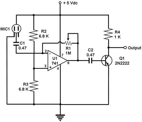
Op Amp-based Sound Detector Circuit
Figure 1. Diagram for a Sound Detector Circuit This is a circuit for detecting sounds and providing an output signal when a sound is detected. This output signal may be fed to another circuit that sets off an alarm when the signal is received. This circuit is therefore useful in security applications. The circuit uses a condenser microphone to pick up sounds from the environment. This is a powered microphone, which makes it more sensitive than ordinary microphones. The microphone transforms the sound waves into an electronic signal that is fed to the 741 op amp. The 741 op amp in this circuit is configured as a single-supply inverting amplifier. Adjust R1 to maximize the sensitivity of your circuit. C1 and C2 are used to block the DC component of the signals, so that only the AC component carrying the sound information reaches the output transistor Q1. Note that the output, which is taken from the collector of Q1, is inverted with respect to the output of the 741 amplifier. This output signal may be used as a triggering signal for a 555-based monostable multivibrator, which outputs one clean pulse every time it is triggered. This clean pulse, in turn, may be used to trigger a tone generating circuit or alarm. |
|