ECE Projects
|
ECE Projects |
Electronic Projects AudioRF
Circuits |
Op-Amp Voltage Regulator Circuit
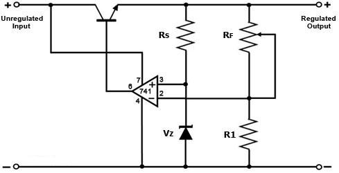
Figure 1. A Simple Op-Amp-based Voltage Regulator Circuit Figure 1 shows a simple voltage regulator circuit that employs an operational amplifier (op-amp). As its name implies, this circuit accepts an unregulated voltage input (i.e., a fluctuating input voltage), and provides a regulated voltage output (a stable output voltage that remains at or very close to its intended output level). The unregulated input voltage must be higher than the desired output level by a sufficient margin in order to achieve 'effective' regulation. The zener diode Vz acts as a voltage reference for the circuit, and is fed into the non-inverting input of the operational amplifier. The voltage divider formed by R1 and RF sets the voltage level of the inverting input of the op amp, which is basically a feedback from the circuit output to the op amp. The NPN transistor is used to boost the output current of the circuit. The voltage at the non-inverting input of the op amp is pegged at the zener voltage, while the voltage at the inverting input is always a fraction of the output voltage as defined by RF and R1. When the output exceeds the set level, the inverting input voltage exceeds that of the non-inverting input, causing the output of the op-amp to go 'low'. This turns off the NPN transistor, causing the output voltage to dip. When the output goes below the set level, the reverse happens, i.e., the op-amp's output goes 'high', causing the NPN transistor to turn on and pull the voltage up. Thus, this circuit works by turning off the transistor when the output voltage is too high and turning it on when the output is too low. This balancing act happens continuously, with the circuit reacting instantaneously to deviations in the output voltage. Resistor RF is adjusted to set the desired output voltage of the circuit. The zener diode needs to be replaced by a voltage reference IC if a more stable and more precise output is required. |
|