ECE Projects
|
ECE Projects |
Electronic Projects AudioRF
Circuits |
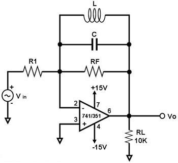
Peaking Amplifier
Figure 1. Circuit Diagram for an Op-Amp-based Peaking Amplifier The circuit shown in Figure 1 has a maximum output (or 'peaks') at a certain frequency. It is said to have a peaking frequency response, hence its name 'peaking amplifier'. The main component of this circuit is the operational amplifier (such as the 741 or 351), which is configured as an inverting amplifier with a parallel LC network in the feedback circuit. This LC network in the feedback path is the one that determines the frequency at which the output of the circuit peaks. This frequency fp is known as its resonant or peak frequency, and is given by: fp = 1 / [2p(sqrt(LC))]. At the resonant frequency, the impedance of the parallel LC network becomes very high. If this impedance is denoted by Rr, then the gain G of the amplifier in Figure 1 at resonant frequency is given by: G = -(RF//Rr) / R1.
|
|