ECE Projects
|
ECE Projects |
Electronic Projects AudioRF
Circuits |
Phase-Locked Loop (PLL) Oscillator
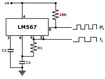
Figure 1. Phase-Locked Loop (PLL) Oscillator Circuit Diagram This circuit is a phase-locked loop (PLL) dual-frequency precision oscillator. The main component of this circuit is the LM567, a general purpose tone decoder designed to provide a 'low' TTL output at pin 8 when the input signal present at pin 3 is within the specified pass band. External components are used to independently set the center frequency, bandwidth and output delay of the LM567. The LM567 has an internal voltage-controlled oscillator that generates a fundamental frequency fo = 1(R1C1) Hz. If this is used as input to pin 3, the pin 8 output will be toggled at a rate that's twice fo. Thus, this precision oscillator circuit provides two outputs to the user - one at the fundamental frequency fo defined by R1 and C1 and another at a frequency equal to 2 fo. |
|