ECE Projects
|
ECE Projects |
Electronic Projects AudioRF
Circuits |
Power Supply Circuit # 1
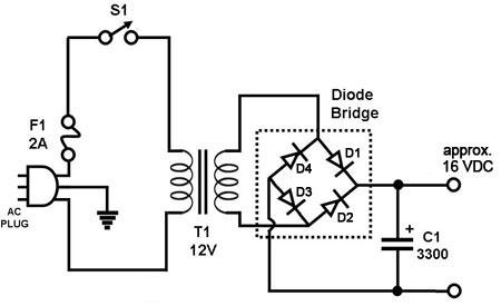
Figure 1. Circuit Diagram for a Full-Wave Rectifier Circuit using a Diode Bridge The circuit in Figure 1 is a basic full-wave rectifier circuit that converts the household AC voltage into a DC voltage. The transformer is used to step the 220 VAC to a lower voltage (12 VAC) in this case. The reduced AC voltage is rectified using the diode bridge circuit shown. In one direction of the current, D1 and D3 are 'on' while D2 and D4 are 'off', charging C1. In the other direction, D2 and D4 are 'on' while D1 and D3 are 'off', also charging C1. The voltage built up by C1 is the useable DC voltage. C1 in this example has a value of 3,300 microF. This is called a 'full-wave' rectifier because diode rectification occurs in both the negative and positive cycles of the AC waveform. Note that the resulting DC voltage is higher than the measured RMS value of the AC voltage by a factor of about 1.414. Thus, in the example above, the voltage at C1 can exceed 16 V DC (assuming no real-world losses). |
|