ECE Projects
|
ECE Projects |
Electronic Projects AudioRF
Circuits |
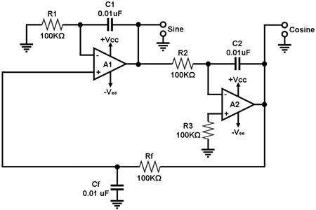
Quadrature Oscillator Circuit
Figure 1. A Quadrature Oscillator Using Two Op-Amps Figure 1 shows a quadrature oscillator that uses two op-amps. A quadrature oscillator is a circuit that generates two periodic signals that are in quadrature, i.e., they are 90 degrees out of phase. The circuit in Figure 1 generates a sine wave and a cosine wave, which were arbitrarily taken from the outputs of operational amplifiers A1 and A2, respectively. This circuit basically consists of two parts: an amplifier circuit consisting of A1 and A2 and a feedback circuit composed of Rf and Cf. A feedback amplifier circuit such as this oscillates because it satisfies the two basic requirements for oscillation: 1) the total phase shift around the amplifier-feedback loop is 0 or 360 degrees; and 2) the magnitude of the loop gain must be at least equal to 1. A1 is configured as a non-inverting integrator whose input is taken from the output of A2 through the Rf-Cf feedback circuit. A2 is configured as a pure integrator that converts the sine wave output of A1 into its cosine output. Note that this circuit satisfies the conditions for oscillation only at a single frequency fo, which is given by: fo = 1 / (2pRC) where RC = R1C1 = R2C2 = RfCf. |
|