ECE Projects
|
ECE Projects |
Electronic Projects AudioRF
Circuits |
R-2R Network Digital-to-Analog Converter (DAC)
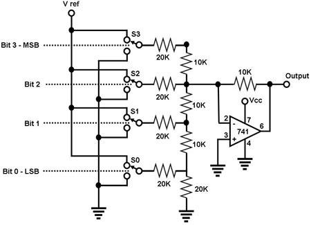
Figure 1. Circuit Diagram for an R-2R Ladder Network DAC The circuit shown in Figure 1 is a simple 4-bit digital-to-analog converter. It is actually just a variant of a simple op amp summer circuit, i.e., an operational amplifier configured to output a voltage that is proportional to the sum of the input voltages. In this circuit, the inputs are binary weighted with respect to each other, with the binary weighting of the inputs achieved by the R-2R ladder resistor network at the non-inverting input of the op-amp. As its name implies, the R-2R network consists of resistors with only two values, R and 2R (10K and 20K, respectively, in the circuit shown). The input SN to bit N is '1' if it is connected to a voltage VR and '0' if it is grounded. The output Vo of an R-2R ladder DAC with N bits is: Vo = VR/2N (SN-12N-1 + SN-22N-2+...+S020). Thus, the output Vo of the 4-bit R-2R ladder DAC in Figure 1 is: Vo = VRef (S3/2 + S2/4 + S1/8 + S0/16) wherein S3, S2, S1, and S0 are the logic inputs ('1' or '0') for bits 3, 2, 1, and 0, respectively. The number of bits of this DAC may be increased by connecting more switches with corresponding R/2R resistors. |
|