ECE Projects
|
ECE Projects |
Electronic Projects AudioRF
Circuits |
Series Voltage Stabilizer Circuits
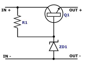
Figure 1. Simple Zener Series Stabilizer Circuit Diagram The circuit in Figure 1 is a simple voltage stabilizer circuit that employs a resistor, a zener diode, and an NPN transistor. In this circuit, the zener diode is used to stabilize the base voltage of the NPN transistor, which carries the load current. The load transistor is in series with the load, which is why this circuit is also known as a series stabilizer. Unlike the amplified zener shunt stabilizer, the dissipation of the transistor increases only when the actual load current increases, making its operation more efficient.
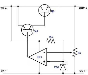
Figure 2. Negative Feedback Series Voltage Stabilizer Circuit Diagram The circuit in Figure 2 is a more complex series voltage stabilizer circuit, utilizing an operational amplifier (IC1) to 'slow down' or turn off the load transistor Q1 when the output voltage is excessive. The zener diode ZD1 in this circuit is just used as a reference voltage for defining the threshold at which the op amp will turn Q2 and Q1 on or off. Because of this negative feedback mechanism, power is consumed more efficiently, since the load is only supplied with current when it needs it. |
|