ECE Projects
|
ECE Projects |
Electronic Projects AudioRF
Circuits |
Simple LED Voltmeter Circuit
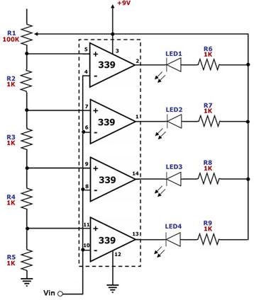
Figure 1. Simple LED Voltmeter Circuit Diagram This circuit is for a simple LED 'bar graph' voltmeter. Each op-amp of the 339 quad operational amplifier is used as a comparator for comparing the input voltage Vin against a corresponding voltage level that's a fixed proportion of the power supply (9V in this case). The voltage levels to which the input voltage is compared may be adjusted through R1. By default, all the LED's are off because the outputs of all 339 op amps are 'high', since each non-inverting input voltage is higher than the corresponding inverting input voltage. As the input voltage rises, it exceeds the threshold voltage set for each op amp one by one, making the corresponding op amp's output low and lighting its LED. Thus, more and more LED's are lighted up as the input voltage rises. More LED's may be added by adding more op-amps connected in a similar manner. Of course, other op-amps may be used for this circuit too. |
|