ECE Projects
|
ECE Projects |
Electronic Projects AudioRF
Circuits |
Simple Logic Probe Circuit
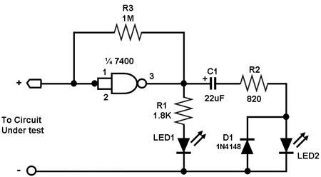
Figure 1. A Simple Logic Probe Circuit Figure 1 shows a simple logic probe circuit. A logic probe is an instrument for determining the logic state of a point or node in a digital circuit. This simple logic probe is capable of determining whether a node is at logic '1', at logic '0', in high impedance state, or pulsing. The input is fed into a NAND gate, which is actually just connected to function as a NOT gate. If the input is 'high', the output of the NAND gate is 'low', causing both LED1 and LED2 to be off. If the input is 'low', the NAND output will be high, causing LED1 to light up. Meanwhile, C1 will immediately charge up when the input is 'low' (NAND output is high), causing LED2 to remain unlit. If the input is in high impedance state (floating), LED1 will just be weakly lit, while LED2 will remain 'off'. LED2 will only light up when the input is pulsing. When the NAND output goes from low to high, LED2 will light up momentarily while C1 charges up. Allowing C1 to fully charge up and stay charged will cause LED2 to turn off permanently (a capacitor behaves like an open circuit to a DC signal). If the NAND output goes from high to low before C1 becomes fully charged, LED2 will not turn off completely, as long as the NAND output goes high again to repeat the cycle. Thus, a pulsing NAND output will allow a certain amount of voltage to remain across LED2 to keep it lit up (a capacitor allows AC signals to pass). |
|