ECE Projects
|
ECE Projects |
Electronic Projects AudioRF
Circuits |
Simple Regulated Power Supply Circuits
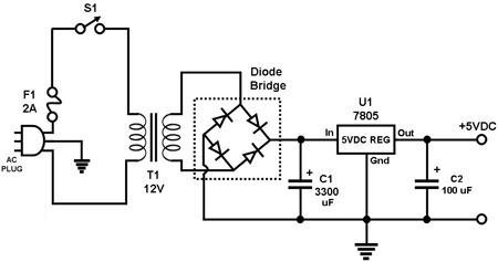
Figure 1. Circuit Diagram for a Regulated Power Supply The circuit in Figure 1 uses a full-wave diode bridge rectifier circuit to convert the household AC voltage to an unregulated DC voltage at capacitor C1. The voltage at C1 is then fed into a voltage regulator IC which outputs a regulated supply voltage, i.e., a voltage that more or less remains at the same level despite changes in load.
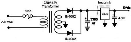
Figure 2. Circuit Diagram for another Regulated Power Supply The circuit in Figure 2 uses a full-wave two-diode rectifier circuit to convert the household AC voltage to an unregulated DC voltage at capacitor C1. The voltage at C1 is then fed into a voltage regulator IC which outputs a regulated supply voltage, i.e., a voltage that more or less remains at the same level despite changes in load. In both examples, the regulator used is the 7805, which outputs 5V DC. A broad range of other DC voltage regulator IC's is available in the market. The voltage regulator must be attached to a heatsink if maximum allowable current is required in its operation. |
|