ECE Projects
|
ECE Projects |
Electronic Projects
AudioRF
Circuits |
Sine Wave Generator Circuit
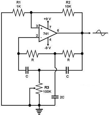
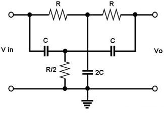
Figure 1. Diagram for a Sine Wave Generator This is a circuit for generating a sine wave from a single operational amplifier. The feedback loop of the op amp in this circuit (741) consists of a twin-T filter connected between its output and its inverting input. Positive feedback for oscillation is provided by R2. The twin-T filter (see Figure 2) is a passive notch filter composed of two T-networks, with maximum attenuation occurring at fn = 1/(2pRC). One of these T networks has one resistor and two capacitors, while the other has two resistors and one capacitor. At the notch frequency fn of the twin-T filter, the total phase shift around the loop gain of this op amp circuit is zero, which satisfies the requirement for oscillation. This is why the circuit generates a sine wave with a frequency equal to fn = 1/(2pRC). Note that variable resistor R3 in the circuit needs to be adjusted (in relation to the chosen value for R) until oscillation occurs.
Figure 2. A Twin-T Filter |
|