ECE Projects
|
ECE Projects |
Electronic Projects AudioRF
Circuits |
Sound-to-'Dancing Lights' Converter Circuit
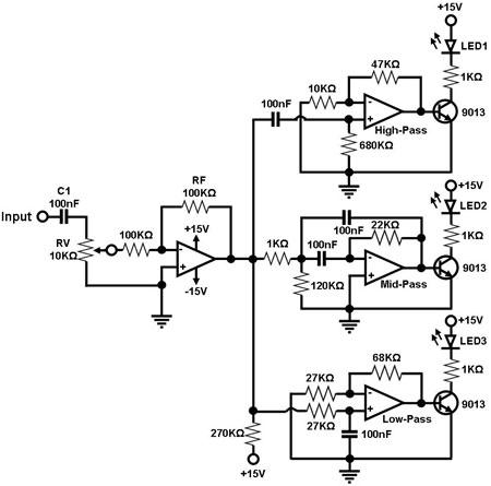
Figure 1. Schematic Diagram for a Simple Sound-to-Light Converter Figure 1 shows a simple circuit for converting an audio signal (such as one that comes from the speaker terminals of a CD player). The circuit basically consists of a buffer/amplifier stage and three filter circuits: a high-pass filter, a mid-pass filter, and a low-pass filter. The output of each filter circuit drives a light-emitting diode of different color. The input signal is fed to the buffer stage through C1. The values of RF and RV1 should be chosen so that the buffer is able to drive the three filters attached to its output. The low-frequency, mid-frequency, and high-frequency components of the input signal are only allowed to pass through the low-pass filter (bottom filter), the mid-pass filter (middle filter), and the high-pass filter (topmost filter), respectively, thus separating them from each other. Changes in the output of a filter cause its corresponding output LED to turn on and off. In effect, feeding a continuous audio signal to the input of this circuit causes the LED's to 'dance'. |
|