ECE Projects
|
ECE Projects |
Electronic Projects AudioRF
Circuits |
Three-Mode Tone Generator Circuit
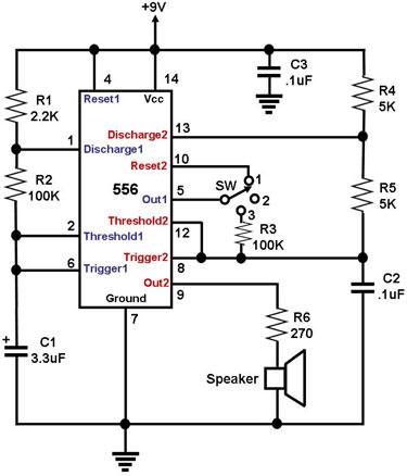
Figure 1. Schematic Diagram for a Three-Mode Tone Generator Figure 1 shows the circuit diagram for a 3-Mode Tone Generator, i.e., a circuit that can produce tones in three different modes. These modes are: 1) a continuous output of tone bursts, 2) a steady tone, and 3) an alternating output of two different tones. The main component of the circuit is the 556, which is basically a single IC with two 555 timers inside. The pins of the first 555 timer are labeled in blue while those of the second 555 timer are labeled in red. The first 555 timer is configured as a basic astable multivibrator. The second 555 is also configured as an astable multivibrator, except that its reset, threshold, and trigger pins have the option of being connected to the output of the first 555 timer as shown in Figure 1. The output tone of the circuit is generated by the second 555 timer, whose output (pin 9) drives the speaker. The type of tone generated by this 555 depends on how the output of the first 555 (pin 5) is connected to it. Switch SW is used to connect pin 5 to one of these three options: 1) the rest pin of 555 # 2 (pin 10); 2) floating; and 3) the trigger/threshold pins of 555 # 2 (pins 8 and 12). When SW connects pin 5 to pin 10 (reset2), the pulses generated by 555 # 1 regularly set and reset 555 # 2 at intervals defined by the oscillation frequency of 555 # 1. As such, the tone generated by 555 # 2 is regularly interrupted by 555 # 1, resulting in a continuous output of 'tone bursts'. The frequency of the tone itself is determined by R4, R5, and C2. When SW disconnects pin 5 from 555 # 2 (floating), 555 # 2 is configured and behaves as a simple astable multivibrator, resulting in a steady tone output. The frequency of this steady tone output is determined by R4, R5, and C2. When SW connects pin 5 to pins 8 and 12 (trigger2 and threshold 2, respectively) through R3, the charge/discharge rates of capacitor C2 change as pin 5 toggles between low and high. This causes the circuit to output two different tones alternately. |
|