ECE Projects
|
ECE Projects |
Electronic Projects AudioRF
Circuits |
Tone Burst Generator Circuit
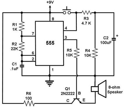
Figure 1. Circuit Diagram for a Tone Burst Generator This is a circuit that generates a tone of set frequency for a duration of time after the switch is pressed and released. The circuit uses a 555 timer IC configured as an astable multivibrator, i.e., it generates a continuous signal of a set frequency as long as its reset pin (pin 4) is held high. When the switch is not yet pressed, pin 4 is pulled 'low' to ground, so the 555 does not output a tone signal. Pressing the switch connects pin 4 to the supply, causing the 555 to start generating the tone signal. The pressed switch also allows C2 to charge up to the supply voltage. When the key is finally released, pin 4 is disconnected from the supply, but the 555 will continue to generate the tone because the voltage across C2 will 'hold' the pin 4 voltage high. The 555 output will only stop oscillating when C2 has discharged to a voltage below the level required to 'reset' the 555. Note that increasing C2 will increase the duration of the tone burst. |
|