ECE Projects
|
ECE Projects |
Touch-Triggered Switch
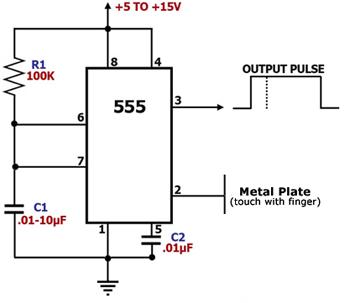
Figure 1. Touch-Triggered Switching Circuit Diagram This is a touch-triggered switching circuit designed to generate a pulse for use by other circuits. The main component of this circuit is the 555, a versatile timer IC. It is configured as a monostable multivibrator, a circuit which will output a single pulse if triggered. It will remain dormant until it is triggered once again to output a single 'shot' of pulse. For this reason, it is also known as a 'one-shot'. The input pin of the 555, pin 2, is very sensitive. Touching pin 2 of the above circuit with a finger is enough to trigger an internal flip-flop to output a 'high' level at pin 3 and initiate the charging up of C1. Once C1 reaches a certain voltage, the internal flip-flop is triggered once again to change state, pulling down the output to 'low' once again. The entire cycle basically produces a pulse at pin 3. |
|