ECE Projects
|
ECE Projects |
Electronic Projects AudioRF
Circuits |
Transistor-based DC Motor Controller (Single Supply)
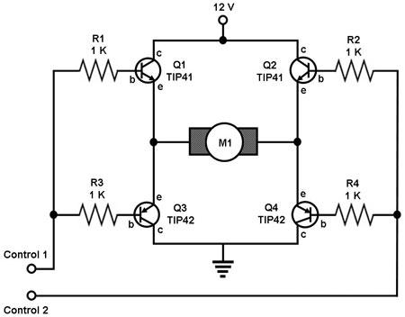
Figure 1. Circuit Diagram for a DC Motor Controller Using Bipolar Transistors This is a circuit for controlling an ordinary DC motor using two pairs of transistors (1 NPN and 1 PNP for each pair). A DC motor runs in one direction if the required voltage is applied across its winding and runs in the opposite direction if the polarity of the applied voltage is reversed. This function can easily be achieved by the circuit above. In this circuit, a 'logic 1' voltage at Control 1 and a 'logic 0' voltage at Control 2 will turn on Q1 and Q4 and turn off Q2 and Q3, causing the motor to turn in one direction. Reversing the voltage levels at Control 1 and Control 2 will reverse the pairs of transistors that are 'on' and 'off', causing the motor to turn in the opposite direction. Putting the same logic input at Control 1 and Control 2 (both '1' or both '0') will cause the motor to stop turning. The values of the base resistors of the transistors (or even the transistors themselves) required by the circuit may be different from those shown in Figure 1, depending on the motor being driven. Experimentation may therefore be required on the part of the hobbyist to make this circuit work. |
|