ECE Projects
|
ECE Projects |
Electronic Projects AudioRF
Circuits |
Ultrasonic Receiver Circuit
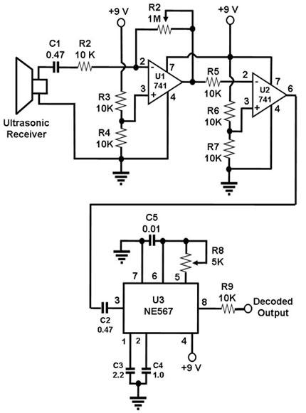
Figure 1. Schematic Diagram for an Ultrasonic Receiver Circuit (capacitor values are in microF) This circuit is used to receive ultrasonic waves from the air that were transmitted by a matching ultrasonic transmitter located somewhere else. Since the ultrasonic receiver used in this circuit is one designed to vibrate optimally at about 40 kHz, the transmitter paired with this receiver must also transmit 40 kHz waves. When these waves hit the receiver, the receiver vibrates and produces electric impulses, also at 40 kHz. These electric signals are amplified by the two op amps in the circuit, the amplified output of which are fed into the 567 IC. This is a PLL tone decoder, i.e., it outputs a signal if it detects an input that is tuned to its set frequency (40 kHz in this case). One example of application of this simple receiver (if paired with a matching transmitter, that is) is as a proximity sensor, such as one that can help a robot avoid running into walls. If used in that manner, the transmitter and receiver transducers must be positioned such that the receiver will only receive echoes of the transmitted signal and not the transmitted signal itself. |
|