ECE Projects
|
ECE Projects |
Electronic Projects AudioRF
Circuits |
Ultrasonic Transmitter Circuit
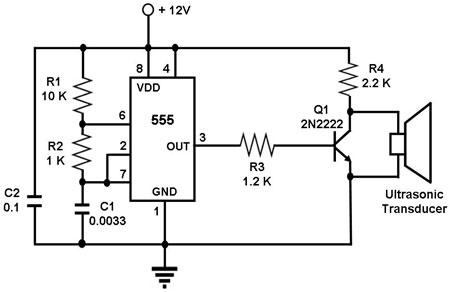
Figure 1. Schematic Diagram for an Ultrasonic Transmitter Circuit (capacitor values are in microF) This circuit is used to transmit ultrasonic waves through air, which are intended to be picked up by a matching ultrasonic receiver. The circuit uses a 555 timer IC configured as an astable multivibrator, i.e., it generates a continuous signal of a set frequency as long as its reset pin (pin 4) is held high. Since the ultrasonic transducer used in this circuit is one designed to vibrate optimally at about 40 kHz, the resistor and capacitor values of the circuit were chosen such that the 555 will output a signal whose frequency is about 40 kHz. This 555 output is amplified by Q1, which drives the ultrasonic transducer. The transducer then vibrates at 40 Khz, generating ultrasonic sound waves of that frequency. If paired with a matching ultrasonic receiver, such a simple transmitter can be used as a proximity sensor, such as one that can help a robot avoid running into walls. If used in that manner, the transmitter and receiver transducers must be positioned such that the receiver will only receive echoes of the transmitted signal and not the transmitted signal itself. |
|