ECE Projects
|
ECE Projects |
Electronic Projects AudioRF
Circuits |
Voltage Squarer Circuit
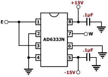
Figure 1. Voltage Squarer Circuit Diagram This is a circuit for squaring an input voltage. The main component of this circuit is the AD633, a low-cost analog multiplier IC. The over-all transfer function of the AD633 is as follows: W = [ {(X1-X2)(Y1-Y2)} / 10V] + Z. Given this transfer function, squaring can easily be achieved by making X1 equal to Y1 and making X2 and Y2 equal to zero. This is done by connecting X1 and Y1 to the same input voltage (E) and grounding X2 and Y2. This is basically the same as connecting the X and Y inputs in parallel with each other. The over-all transfer function of this circuit is as follows: W = E2/(10 V). The output of this configuration is always positive regardless of the polarity of the input. To get a reverse output polarity, just interchange either the X or Y inputs. Primary Reference: Analog Devices Datasheets for the AD633 |
|