ECE Projects
|
ECE Projects |
Electronic Projects AudioRF
Circuits |
Windows Comparator Circuit
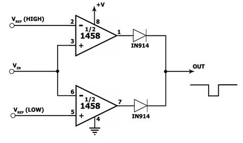
Figure 1. Window Comparator Circuit This is a window comparator circuit that employs a dual op-amp IC, the 1458. This window comparator compares an input signal to a 'low' and a 'high' reference voltage level (VRef Low and VRef High, respectively), and outputs a logic low level if it falls between these two reference levels. If the input is higher than VRef High or lower than VRef Low, the output goes to logic high. One of the op amps is used for comparing the input to VRef High while the other op amp is used for comparison with VRef Low. The IN914 diodes are used to isolate the outputs of the two op amps from each other. |
|